Introduction: Using Node-Red with The-Black-Box
The device The-Black-Box allows access to the hardware interfaces via a Node-RED-based software interface. Node-RED (see also https://nodered.org) offers a graphical low-code programming language that is easy to use in a web browser. The flowchart-like programming language consists of so-called nodes and connections between them. Data is exchanged via messages that are exchanged between two nodes. The following section introduces the basic use of the nodes provided by The-Black-Box.
There are two basic approaches available for communicating with The-Black-Box via Node-RED. On the one hand, the Node-RED server integrated in the device can be accessed. This is the simplest option, as no separate software needs to be installed. All that is required is a web browser. On the other hand, it is also possible to communicate with The-Black-Box via an external node-RED server, i.e., a local server or one running in the cloud. A combination of the two approaches is also possible. Furthermore, it is possible to access multiple devices in parallel.
Due to the stateless behavior of The-Black-Box parallel access via the Node-RED interface and via applications on the command line is also possible. However, it should be noted that the behavior of the connected peripherals can lead to unexpected behavior during parallel access, especially during write access. In this case, the specifications for the connected sensor or actuator should be consulted.
Unless otherwise specified, the following assumes that the integrated Node-RED server is being accessed.
Basics
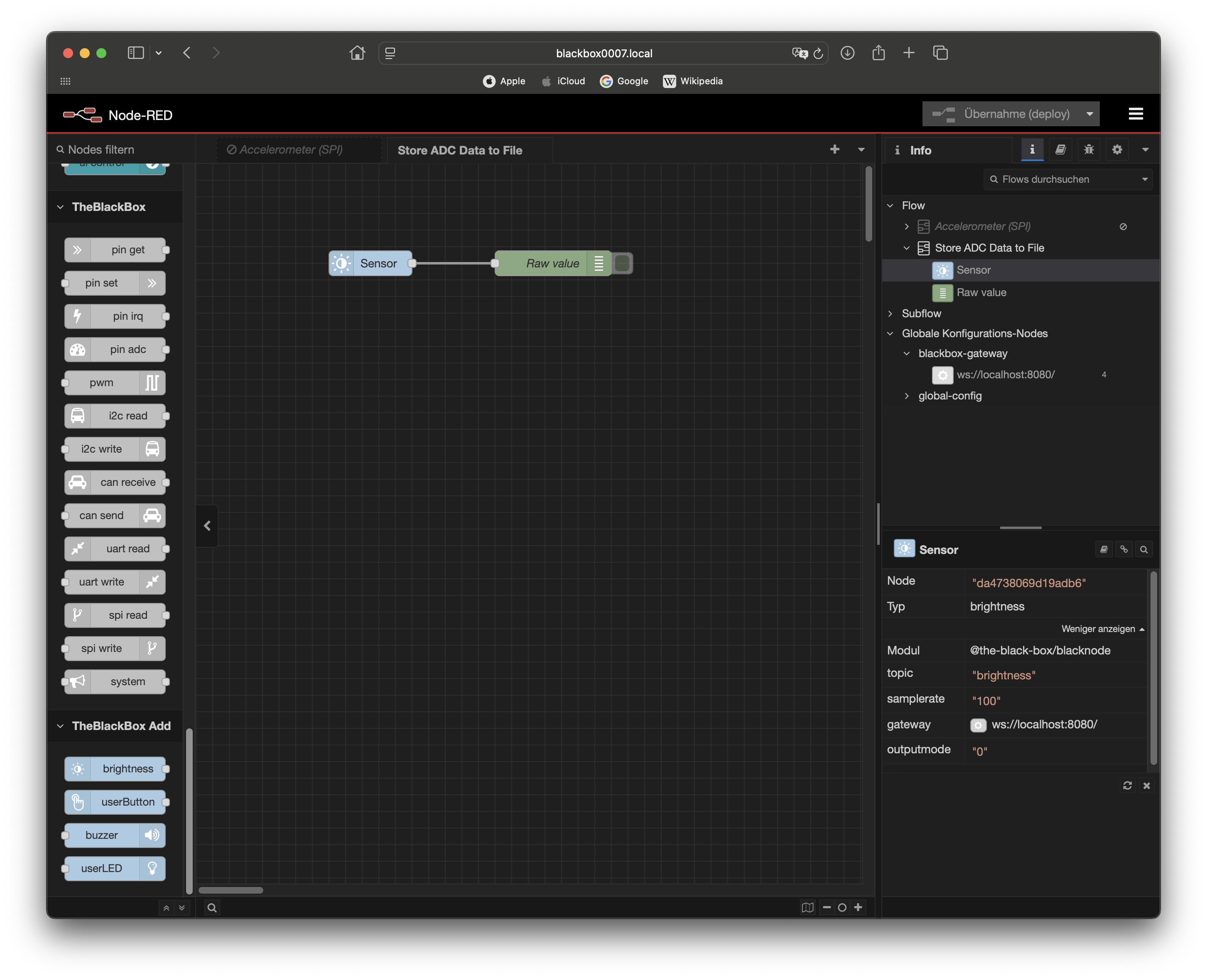
The initial screen opening an example flow.
The figure above shows the initial page when accessing the node-RED server. In this case, a simple example can be seen in the middle of the page. On the left side, the individual standard nodes (colored gray) are listed, which enable access to the integrated hardware. There are also additional nodes (colored light blue) that provide somewhat simplified access to the integrated peripherals (user button, user LED, sensor, and buzzer). If advanced configuration of the integrated peripherals is necessary, the standard nodes should be used. Several settings options and additional outputs are visible on the right-hand side.
Note
It should be noted that the node-RED server is configured by default and all functionality required to access the hardware is provided by the nodes mentioned. The layout in the browser can be extensively configured by the user. For this reason, the actual appearance may differ from the screenshot shown.
Access to the hardware divides the nodes into two groups. One group performs read access, i.e., one or more values are queried. The second group performs write access, i.e., one or more values are changed. The following section presents the two nodes pinget (read access) and pinset (write access) as examples.
Note
At this point, it should be noted once again that access to the hardware from The-Black-Box is only possible
if it has been correctly configured beforehand using the systemset command.
Read Access
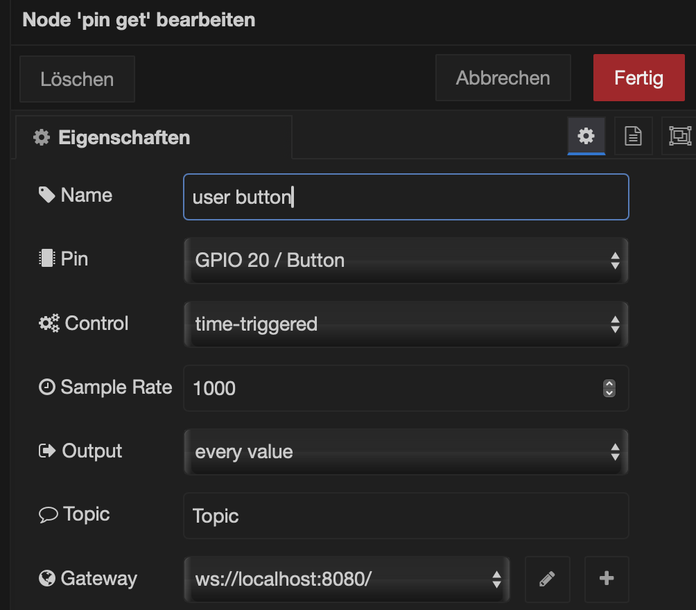
Using the time-triggered control the value is read with constant sample rate.
The pinget node reads a value from a digital input. In the example shown above, the current value of the
integrated user button is read (which is Pin #20). The parameter Name changes the visual node’s name in the
flow. There are generally two ways to initiate the readout using Control.
One is the time-triggered mode, i.e., the current value is queried at a constant sampling rate (can be configured
using Sample Rate) and output via the node’s output. The second control mode is event-triggered. This option is described below.
In the example, the digital value of the button is queried continuously at a period of 1000 ms. It is possible
to output every value or only changes (using Output), i.e., at edges. By specifying a Topic, the output
value is assigned a corresponding label, which can then be filtered, etc. in subsequent nodes.
The last configuration parameter, Gateway,
describes which The-Black-Box device is being addressed. As described at the beginning, the local or a remote
Node-RED server can be accessed. In this example, the local Node-RED server accesses the corresponding digital input.
If a non-local device is to be accessed, the network address can be specified here. The corresponding port 8080 must
be added, separated by a colon. The gateway is modeled as a configuration node in Node-RED, i.e., it only
needs to be created once and can then be used in different nodes and flows.
This parameter allows multiple The-Black-Box devices to be accessed in a flow. To do this, simply create another configuration node with the corresponding network address.
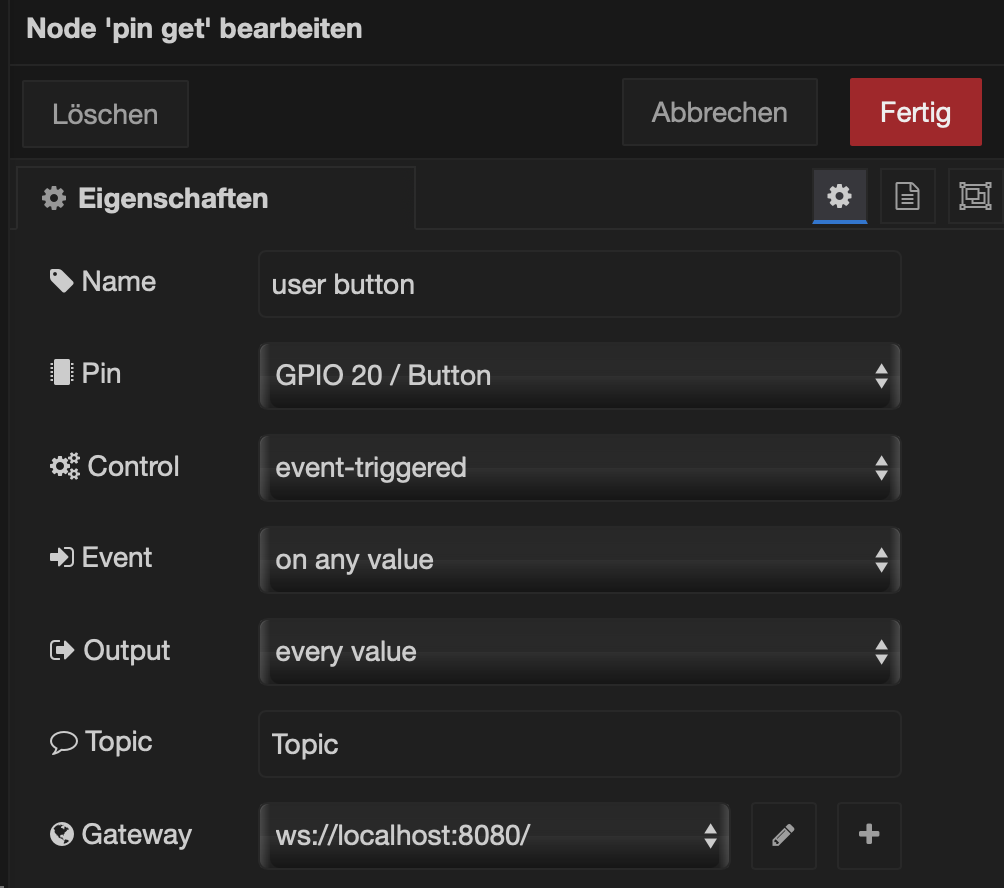
Alternatively, the node can be controlled in event-triggered mode via an incoming message.
If, on the other hand, the node is to be controlled by an external event, the event-triggered control mode
must be configured (see above using Control). The node then receives an input (left side of the node) in addition to the
output (right side of the node). It is possible to respond to different events using the Event parameter. For
example, the readout process can be triggered by any incoming message manually via an inject node
(standard node in Node-RED).
Write Access
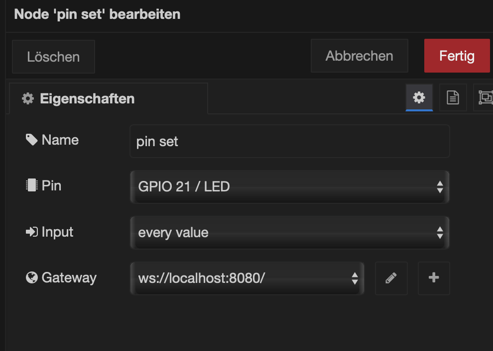
Only few parameters are required to set a digital output value.
The configuration of a pinset node is much simpler, as shown in the figure above. In addition to the Name,
Pin, and Gateway parameters, which are similar to those of the pinget node, the behavior at the Input
must be configured. The node can switch the corresponding digital output for every input value or only
for changes in the value.
File Access
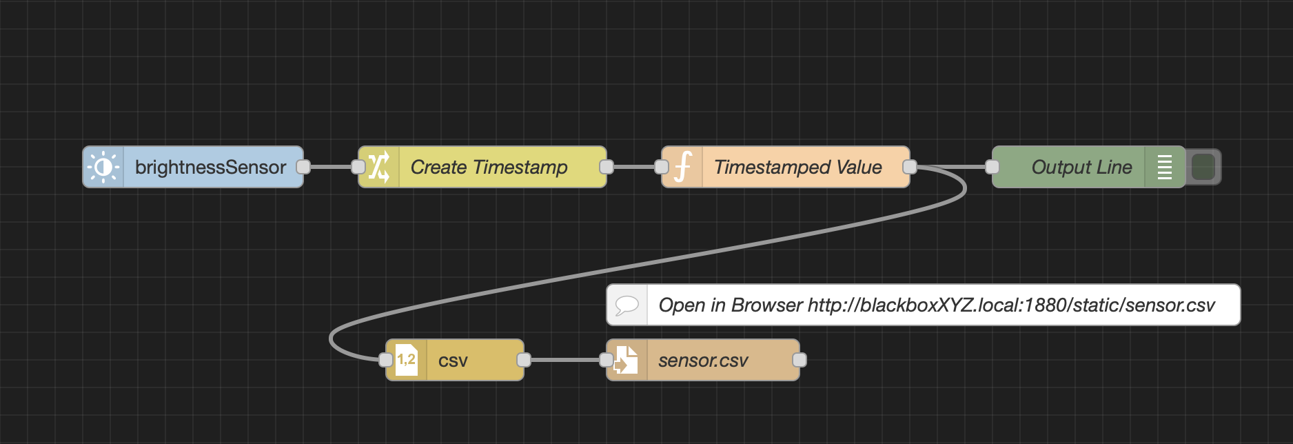
A simple flow writing sensor data into a file using standard nodes.
A common use case is to record sensor data over a longer period of time and temporarily store it for further
processing (e.g., with Excel or Matlab). The device has an internal permanent memory in which data from a
flow can be stored. The path is /home/blackbox/static/. Files can be created and copied here. This memory
area is retained after a system reboot.
The flow shown above reads the internal brightness sensor and processes the value through several steps before writing it line by line to a file. First, the sensor data is timestamped, which requires a change node and a function node. Both nodes are available as standard nodes in Node-RED.
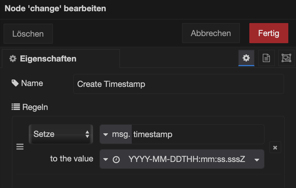
The ‘change’ node creates add a timestamp to the input message data.
The change node (see above) adds an additional field called timestamp to the message, which
contains the current timestamp. The following function node (see below) formats the message into a
two-dimensional array, which is then processed as input by the csv node.
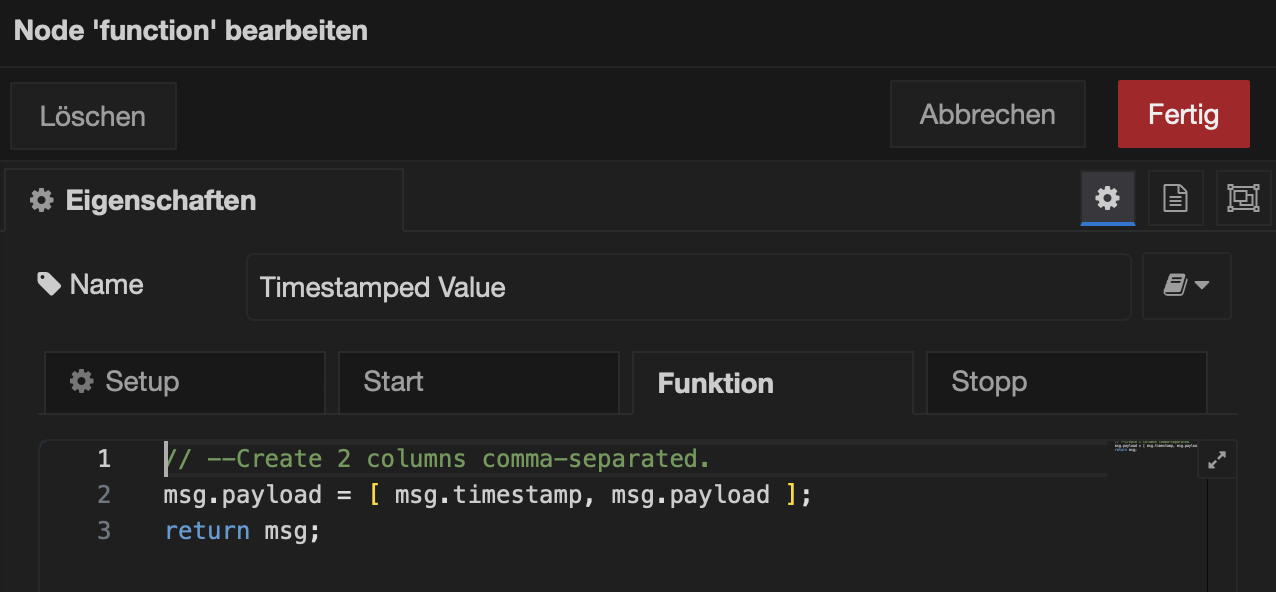
The ‘function’ node outputs a two-dimensional value, a timestamped sensor data entry.
Finally, the data is written to a file named sensor.csv using a write file node (see below).
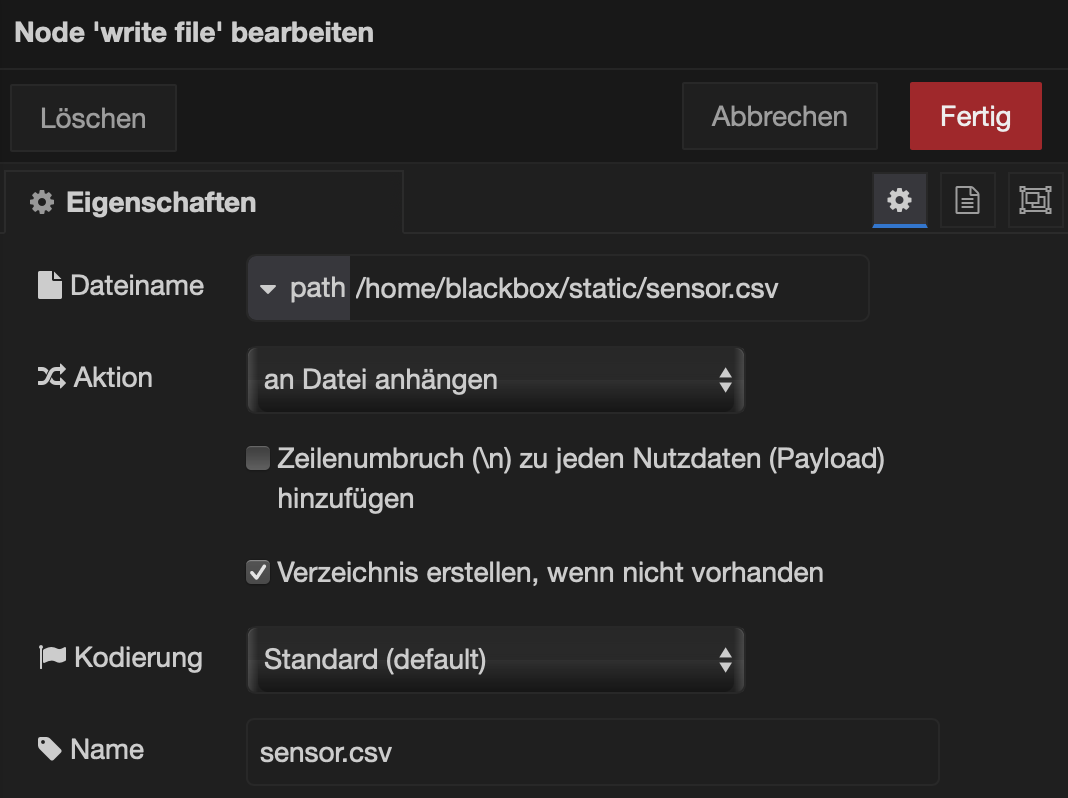
The ‘write-file’ node gets the comma-separated entry and writes to fhe given file.
The recorded file can be read using http GET. In the simplest case, this can be done via the browser or
alternatively via the command line, for example with the curl command (see https://curl.se). The URL for the
file is derived from The-Black-Box device address using port 1880, the static path static/, and the file name,
e.g. http://blackbox0007.local:1880/static/sensor.txt.
Note
Since the files are stored permanently and are not automatically deleted, the user is responsible for deleting files that are no longer needed.