The-Black-Box Device
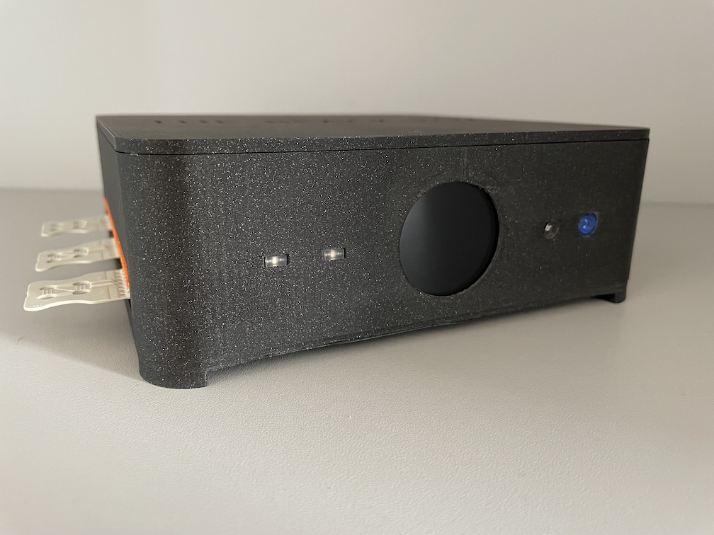
The-Black-Box device has a minimalist, reduced exterior design with a central display on the front.
The-Black-Box device (see above) makes it possible to read from and write to hardware interfaces via a general software message interface. This makes it possible to address peripheral components in a project without having to develop cumbersome software for an embedded target. The application software can simply be run on a host computer (Microsoft Windows, Linux or MacOS) and accesses the connected hardware via a TCP/IP network.
System Architecture
The system architecture follows the structure of a client-server model. The server is accessed via a gateway, which establishes a session with client applications and processes incoming and outgoing messages from the server. The gateway and the server are integrated in the device, the client application can be executed on a host computer or internally in the device. The server is (almost) stateless and can serve any number of client applications. In addition, a single client application can address several devices. The latter is necessary, for example, if the number of interfaces on a single device is insufficient.
Hardware Interfaces
On the back and on the left-hand side, The-Black-Box device has a nine-pin CAN socket, sockets for a 3.3V and 5V power supply and several connector headers for connecting external peripherals.
In addition, further functions are integrated into the device that can be used without external wiring:
User Push-Button (rightmost with Power LED, GPIO #20)
User LED (green, left of main display, GPIO #21)
Light Sensor (right of the main display, GPIO #22)
Buzzer (GPIO #23)
The user LED and the buzzer are connected via digital outputs, the user push-button via a digital input and the light sensor via an analog input (ADC). The integrated functions are available for testing purposes and can easily be used, for example, for the initial testing of software applications.
To be able to use the individual functions, they must first be configured. The integrated functions are configured by default and their functionality cannot be changed at all or only to a very limited extent.
Front Panel
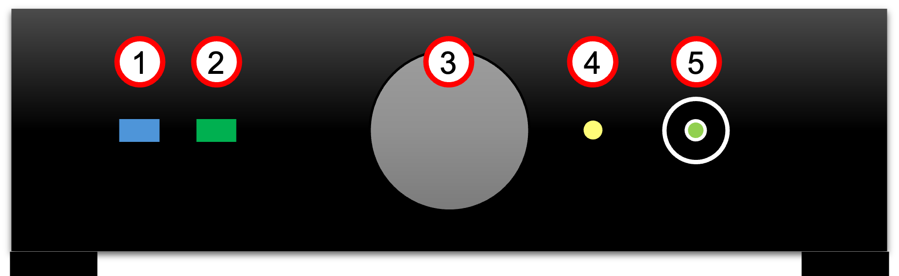
Front Panel View of The-Black-Box Device.
The front Panel of the device is shown in the figure above. (1) shows a blue-colored Bluetooth LED as a status indicator for Bluetooth connectivity on The-Black-Box and indicates that the device is either successfully connected to another device (acting as the initiator) or that another device is in the process of connecting to The-Black-Box (acting as the responder).
The green user LED (2) features a power LED that indicates whether the device is powered on. The main display (3) provides information about the current status of the device and the running applications.
A built-in Brightness Sensor (4) serves as an effective initial method for incorporating sensor functionality within the software for small tests. This sensor continuously monitors ambient light levels and provides real-time data to the system. It is internally connected to GPIO #22.
With the user push button (5), The-Black-Box provides a first input device for incorporating user interaction within the software during initial tests. It provides a tactile interface for users to send commands or trigger specific functions within the system and is internally connected to GPIO #20.
The push button also integrates a user LED providing visual feedback on the status of the device or running applications and can be freely used by the software application without external wiring. It is internally connected to GPIO #21.
Note
The power LED cannot be programmed by the application.
WAGO Connectors (left panel, female)
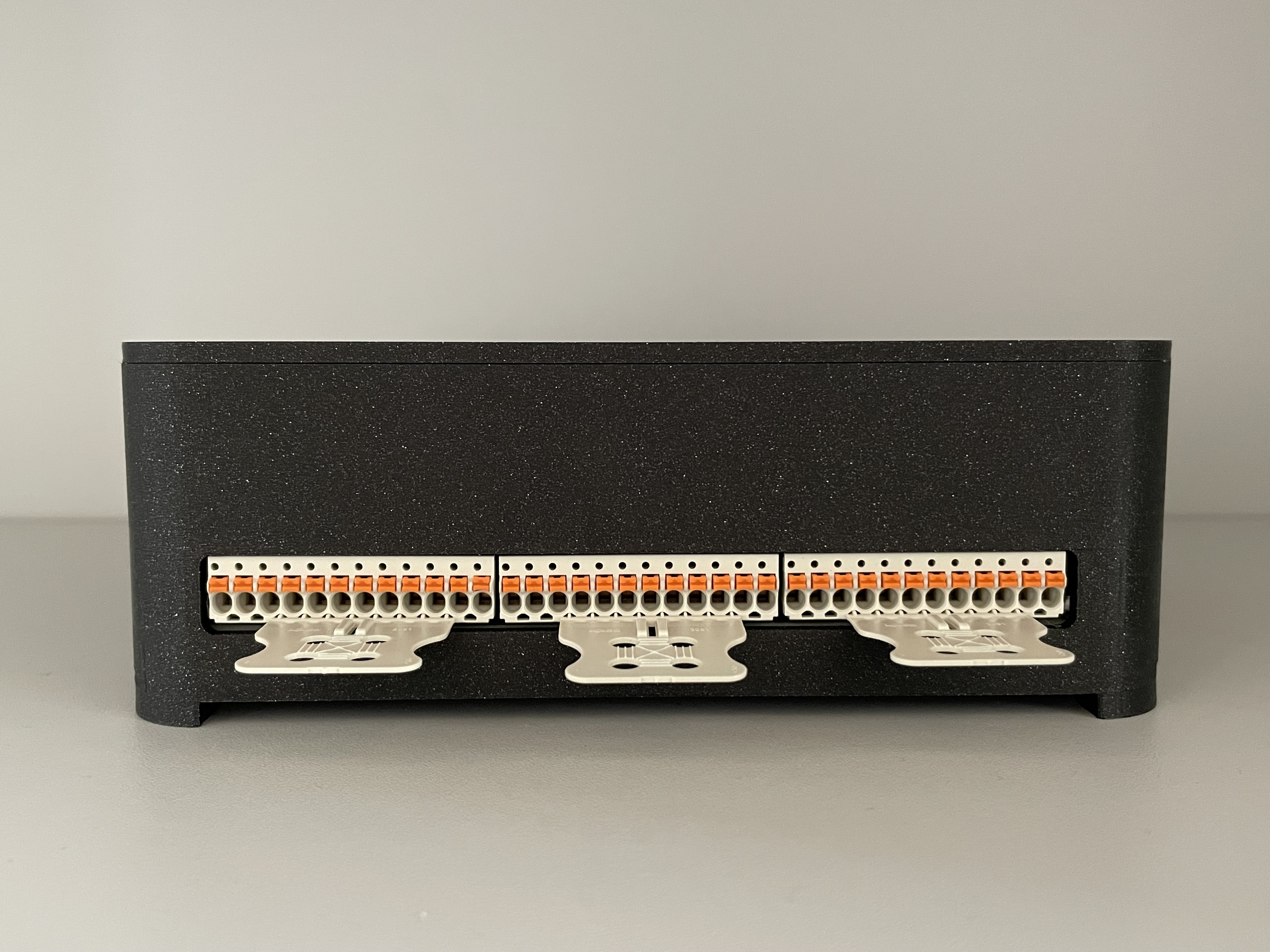
The essential, configurable interfaces of The-Black-Box are located on the left side.
There are 3 WAGO pin connectors on the left-hand side (see above), each with 12 pin headers. All three pin headers have in common that pin 1 and pin 2 (the numbering starts from left to right) lead out the operating voltage of 3.3V (vcc) and ground (gnd) respectively. The following additional functions are available:
SPI (spi): single interface with mosi/miso/clock lines
Digital Out, In, Counter-like Interrupt (io): 11 pins #0 - #10
Analog In (adc): 4 pins #16 - #19
PWM Out (pwm): 4 channels cha0 - cha3
UART (uart): 2 serial interfaces with tx/rx lines
I2C (i2c): 2 bus interfaces with sda/scl lines
Note
All functions has to be configured initially using systemset command before usage.
1 |
2 |
3 |
4 |
5 |
6 |
7 |
8 |
9 |
10 |
11 |
12 |
|---|---|---|---|---|---|---|---|---|---|---|---|
pwr |
pwr |
spi |
spi |
spi |
io |
io |
io |
uart |
uart |
uart |
uart |
vcc |
gnd |
mosi |
miso |
clk |
#0 |
#1 |
#2 |
tx0 |
rx0 |
tx1 |
rx1 |
The left-hand of the three pin headers (see above) implements the SPI bus, several digital inputs or outputs and two serial interfaces.
Note
The SPI interface ist not implemented yet.
Note
The UART 0 is used for internal debug purposes. Please use UART 1.
1 |
2 |
3 |
4 |
5 |
6 |
7 |
8 |
9 |
10 |
11 |
12 |
|---|---|---|---|---|---|---|---|---|---|---|---|
pwr |
pwr |
i2c |
i2c |
io |
io |
io |
io |
adc |
adc |
pwm |
pwm |
vcc |
gnd |
sda0 |
scl0 |
#3 |
#4 |
#5 |
#6 |
#16 |
#17 |
cha0 |
cha1 |
1 |
2 |
3 |
4 |
5 |
6 |
7 |
8 |
9 |
10 |
11 |
12 |
|---|---|---|---|---|---|---|---|---|---|---|---|
pwr |
pwr |
i2c |
i2c |
io |
io |
io |
io |
adc |
adc |
pwm |
pwm |
vcc |
gnd |
sda1 |
scl1 |
#7 |
#8 |
#9 |
#10 |
#18 |
#19 |
cha2 |
cha3 |
The center and right pin headers (see above) have an identical structure. They provide an I2C bus, several digital inputs and outputs, 2 analog inputs each and two PWM output channels.
Various Connectors (rear panel)

A CAN interface is integrated on the rear panel in addition to the 5V output.
Further interfaces (see above) are implemented on the back of the device (from left to right). There is another WAGO connectors next to the Ethernet interface. In the middle of the box is the power supply via USB-C, next to it a reset button and a CAN connector.
1 |
2 |
|---|---|
pwr |
pwr |
5.0V |
gnd |
System Setup (Quick Starter)
Ensure you have a LAN cable and a powered router with available LAN ports. No internet connection is required to use The-Black-Box. The device includes built-in Node-RED (Version 4, see https://nodered.org) support and provides a local instance of Node-RED. When properly connected to your LAN, the local Node-RED server can be accessed at
http://<THE-BLACK-BOX-IP>:1880/
This version of Node-RED comes with all required extensions pre-installed.
Preparing
Locate the LAN port on the rear panel of The-Black-Box.
Plug one end of the LAN cable into The-Black-Box ‘s LAN port.
Connect the other end of the LAN cable to an available LAN port on your router.
Power Up
Ensure The-Black-Box is powered using the USB-C port.
The power LED (within the user push button) should illuminate, indicating that The-Black-Box is operating.
Network Connecting
The-Black-Box is pre-configured to use DHCP by default, meaning it will automatically obtain an IP address from the router. No manual network configuration is needed.
In some cases, due to security requirements, new devices may not receive an IP address via DHCP. For such situations, the MAC address of The-Black-Box is provided on a label underneath the device.
To access The-Black-Box, the router’s DHCP client list for the assigned IP address may be checked. The IP address is also printed on the main display.
Connect to Integrated Node-RED Server
Use your preferred internet browser to connect to The-Black-Box using the IP-address given by your LAN-router.
The Node-RED editor should show up on the left side several The-Black-Box nodes to interact with the hardware interfaces.
Start to Design Your Own Flows
Enjoy!
By default, the device is only configured to use the integrated peripherals such as the user LED, the push button,
the buzzer and the brightness sensor. To use external peripheral devices connected to the lines on the left panel,
the corresponding connection must be configured and switched on via the command line. To do this, use the systemset
command on the command line. Further information can be found in the enclosed HTML documentation.
Note
Without a correct and complete configuration of the external inputs and outputs, they cannot be accessed!